Empowering Sustainability with Convenience & Speed
For EV owners, fast DC chargers are game changers. These devices power up to 80% of the state of charge (SOC) in less than 30 minutes, compared to other charging methods, which can take hours, if not overnight, to complete.
Fast DC charging requires high-voltage, robust components and strict safety standards to provide the ideal experience for EV drivers. Silicon carbide technology helps maximize efficiency and speed up charging times while increasing power density and reliability.
A quick comparison of the three main types of EV charging classifications* is all it takes to see just how much faster off-board charging can be:
| Level | Charger Location | Typical Use | Energy Supply Interface | Voltage Range | Power Level | Charging Period |
| Level 1: Residential | On-board, 1-phase | Home or office | Convenient, everyday outlet | 120V - 240V | Up to 2 kW | 6 – 20 hrs |
| Level 2: Commercial | On-board, 1- or 3-phase | Dedicated outlets | Dedicated outlet | 240V to 400V | 4 to 20 kW |
1 phase: 3 – 4hrs3 phase: 1 – 2 hrs |
| Level 3: Fast Chargers and Tesla Superchargers | Off-board, 3-phase | Commercial filling station/charging | Dedicated EVSE (adapter) | 480V to 600V or Direct DC | 50 to 100 kW |
20 to 30 mins |
(*As of August 2023. Ranges, charging times, and technologies are evolving and will change over time.)
How do fast DC chargers work?
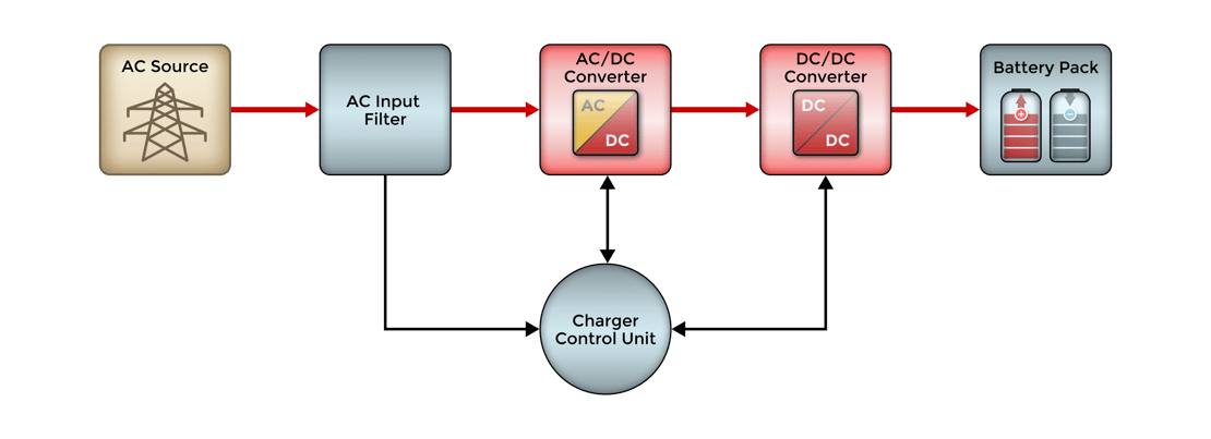
A two-step process converts AC power from the grid to high-voltage DC power, which must be converted to a lower voltage for properly charging the vehicle’s DC battery.
Block Diagram
Step 1 - AC to DC Conversion
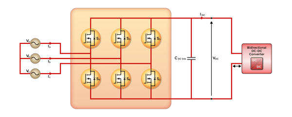
The unstable AC power from the grid is converted to a stable DC link voltage of approximately 800V via a 3-phase full bridge power factor correction (PFC) rectifier.
Step 2 - DC to DC Conversion
In the second step of the process, the sub-unit power converter reduces the incoming high-voltage DC link (approx. 800V) to a lower voltage appropriate for the vehicle’s battery.
The process bypasses the vehicle's on-board charger and sends the lower DC voltage straight to the battery, which is already DC power.
By skipping the on-board conversion process, charging time is a fraction of what it would be in the Level 1/Residential or Level 2/Commercial charging methods, which work with the vehicle’s on-board charger (OBC) to convert the power from AC to DC.
Here are two common ways the DC-DC conversion takes place within the second stage of the sub-unit power converter:
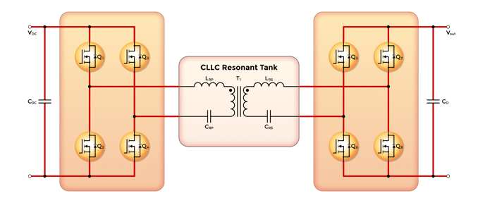
CLLC DC-DC Converter
A capacitor-inductor-inductor-capacitor (CLLC) DC-DC converter uses a symmetric resonant network for bidirectional power distribution. The converter is highly efficient since the LLC resonant tank has zero voltage switching capability.
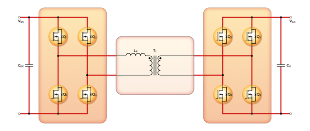
Dual Active Drive (DAB) DC-DC Converter
This bidirectional DC-DC converter utilizes identical primary and secondary side full bridges, known as dual active bridges. A high-frequency intermediary transformer delivers galvanic isolation.
Design Considerations for DC Fast EV Chargers
When designing off-board chargers, engineers should consider the following:
- Charging speed - must be appropriate to the EV’s battery size and capacity
- Safety - built-in safety measures such as overcharge protection, short-circuit protection, and thermal management
- High-voltage capability - a high-voltage, low-current approach is recommended to minimize losses and improve efficiency
- Efficiency - maximized energy delivered to the EV battery, minimal energy losses
- Cost - upfront and ongoing operating costs should be considered
- Compatibility - the system must be compatible with the battery and EV, including voltage and current
- Scalability - design for broad use with a range of EVs and battery sizes
- Environment - must perform reliably in harsh conditions or extreme temperatures
- Industry standards - compliance with applicable industry regulations is essential, including the EV-specific standards Combined Charging System (CSS) and CHAdeMO
Recommended Products
No matter your DC fast charger's power topology or requirements, MCC has the components to help you design the optimal solution.
AC/DC Converter |
||
SiC MOSFET: SICW080N120Y
|
SiC MOSFET: SICW080N120Y4
|
SiC SBD: SICB5060XY
|
SiC SBD: SICPT5060Y
|
SiC SBD: SICB20120Y
|
SiC Schottky Barrier Rectifier: SICPT40120YA
|
IGBT Discrete: MIW75N65F
|
IGBT/PIM Module: MIP75R12E2TN
|
IGBT/PIM Module: MIP100R12E2TN
|
Power MOSFET: MSJPF20N65A
|
|
|
DC/DC Converter |
||
SiC MOSFET: SICW080N120Y
|
SiC MOSFET: SICW080N120Y4
|
SiC SBD: SICB5060XY
|
SiC SBD: SICPT5060Y
|
SiC SBD: SICB20120Y
|
SiC Schottky Barrier Rectifier: SICPT40120YA
|
IGBT Discrete: MIW75N65F
|
|
|
As drivers demand faster, more convenient charging options for their EVs, manufacturers must deliver reliable solutions. MCC Semi is your total solutions partner for DC fast chargers and beyond.
Explore MCC’s diverse solutions for auto and EV applications, including:
Electric Power Steering (EPS)
Body Control Module (BCM)
Interior Lighting
Exterior Lighting
Infotainment
Instrument Cluster
On-board Charger (OBC)
Battery Management System (BMS)
DC-DC Converter
Advanced Driver Assistance System (ADAS)
Seat Control
Contact us to request a sample or discuss your design needs.
.png?width=50&height=50&name=mcc%20150x150%20(1).png)
