Optimizing This Crucial Component for Electric Vehicles
Battery management systems are found in many markets and applications, including Industrial and Renewable Energy. But for hybrid electric vehicles (HEVs), plug-in hybrids (PHEVs), and full electric vehicles (BEVs) they’re essential for safe and reliable operation.
These innovative systems provide real-time data collection to:
- Optimize battery performance
- Alert the driver/operator of issues and malfunctions
- Communicate the battery’s state of charge (SOC) or amount of energy currently available
- Communicate the battery’s state of health (SOH) or remaining capacity/life
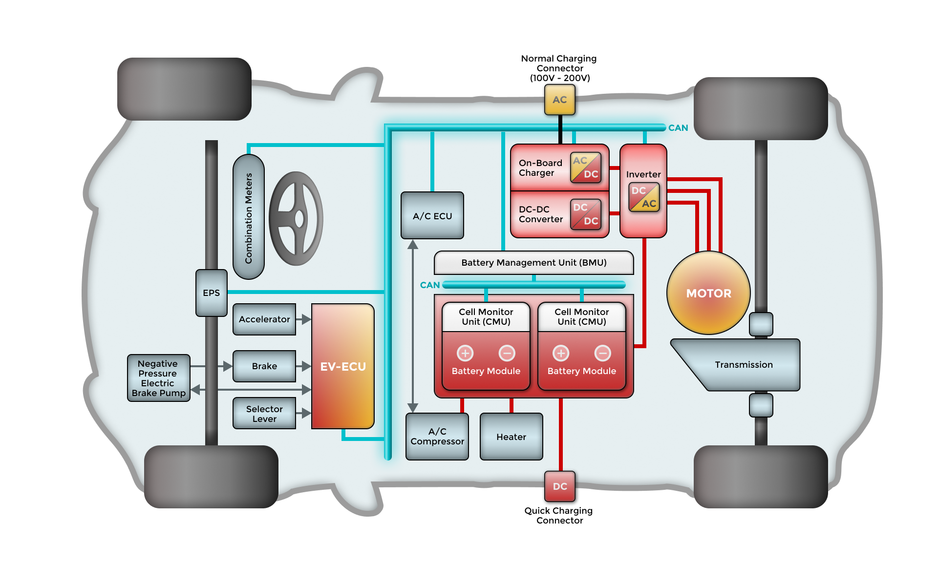
A Battery Management System (BMS) is key to facilitating seamless communication within an electric vehicle, both internally and externally. Internally, a BMS uses sophisticated controllers that communicate at a cellular level, ensuring each battery cell is monitored and managed efficiently. This level of communication is crucial for maintaining optimal performance and prolonging battery life.
Internal Communication
For high-level voltage BMS, internal communication is robust, utilizing advanced controllers to manage the intricacies of the battery cells. In contrast, low-level centralized BMS focus on basic tasks like measuring cell voltage. In modular and distributed architectures, internal communication must overcome challenges like voltage shifts between cells. This can be addressed through software protocols or hardware solutions such as optical-isolators or wireless communication, ensuring reliable data transfer.
External Communication
Externally, BMS employs a centralized controller to interface with connected devices. This communication can vary in complexity, depending on the device, and may use methods like serial communications, CAN bus, and DC-BUS communications. These methods are essential for transmitting critical information about the battery's status to both the vehicle's systems and the driver, enhancing overall safety and efficiency.
By addressing these internal and external communication needs, the BMS not only optimizes battery performance but also ensures that the vehicle remains responsive to changes in battery health and charge status. This comprehensive communication strategy is vital for the smooth operation of electric vehicles, enabling them to meet the demands of modern transportation
Continuous Monitoring
The BMS provides a constant feedback loop by analyzing voltage, temperature, and current. This helps drivers maintain safety while maximizing the driving range on a battery’s charge. The system uses this information to prolong battery life by stopping the charge function when full and shutting down operations when overheating.
To achieve optimal energy utilization, the BMS employs sophisticated monitoring techniques. It vigilantly monitors the battery's state, ensuring that voltage, current, and ambient temperature remain within safe limits. This continuous surveillance is crucial for preventing overcharging and over-discharging, which could lead to premature battery degradation and energy inefficiency.
Seamless Charger Communication
Additionally, the BMS communicates seamlessly with the onboard charger. This interaction ensures that the charging process is controlled and efficient, maximizing energy intake without risking damage. By optimizing stored energy, the BMS not only extends the range of the vehicle but also enhances the overall reliability and safety of the battery system.
Battery management systems must be designed to incorporate the appropriate levels of:
- Overcharge protection
- Over-discharge protection
- Short circuit protection
- Thermal runaway protection
Charging and discharging must be carefully managed throughout the life of the battery. Initially, the BMS will not charge the battery to full capacity, as later in its lifecycle, it will need more charge to hit the desired range. Additionally, the rate of charge in each battery cell will vary (even in a new battery), creating the need for constant balance/equalization.
How do battery management systems work?
The typical BMS setup includes multiple lithium-ion batteries connected to a control unit and sensors by connection wires.
While there is currently no global standard, the power topographies are typically set up in one of two ways:
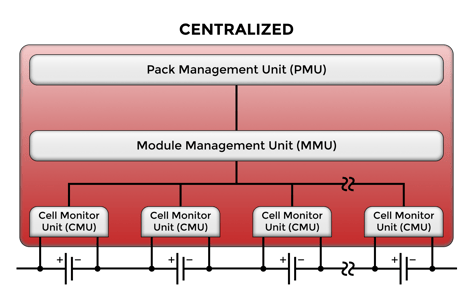
Centralized architecture
With a centralized architecture, one controller unit manages all of the battery cells. This single assembly board is simpler to design but can be bulky and costly. Also, if one battery cell fails, the whole unit must shut down as a safety measure.
Primary-secondary architecture
With the primary-secondary or decentralized architecture, the cell monitoring and intelligence circuitry are monitored by multiple control units. One advantage of this architecture is if one cell fails, the others are still able to function.
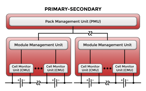
One primary function of the BMS is balancing the battery cells, which each have their own rate of charge at any given time. The battery monitoring integrated circuit (BMIC) monitors the individual cells in real time, then informs the cell management controller and battery management controller. This can be achieved in two ways:
Passive cell balancing - energy is dissipated from the battery’s most-charged cell in the form of heat, which may impact overall performance and efficiency.
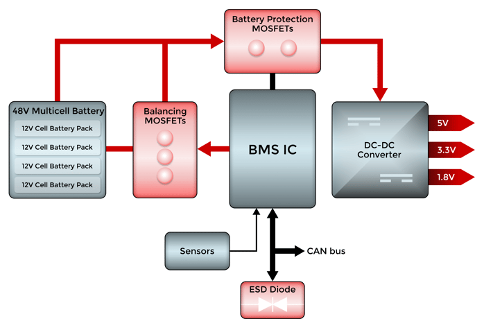
Active cell balancing - instead of dissipating the extra energy when a cell reaches higher voltage, it transfers that excess energy to another battery cell with lower levels of charge. A low equivalent series resistance (ESR) MOSFET is utilized as a power switch to help minimize energy loss.
A protection device is used to help safeguard this vital EV component from harmful electrostatic discharge (ESD).
EV BMS Block Diagram
Design Considerations
Compared to other parts of the vehicle, the EV’s battery system is the most expensive. Therefore, the BMS can make or break the performance and longevity of the EV itself. Proper component selection is key to a BMS drivers can rely on. Critical requirements include:
- Charge/discharge - cell balancing by charging and discharging of individual cells with different levels of charge can impact the overall performance and life of the battery.
- Energy efficiency - lower energy usage enhances fuel economy and requires less power from the vehicle’s battery, which improves the range for EVs.
- High-temperature capability - components must withstand the worst-case scenario in thermal surges caused by torque assistant pulses.
- High current handling - the system should perform reliably under the worst possible conditions and current surges. BMS components must provide overvoltage protection (OVP).
- ESD protection and transient suppression - in addition to protecting from high heat and current, the BMS design should provide the appropriate levels of protection from electrostatic discharge and ensure any transients are effectively managed.
- Low on-resistance - minimizing heat generated during operation extends the life of the component, and low RDS(on) plays a crucial role while enhancing system responsiveness.
- Fast switching speed - switching should be fast enough to ensure smooth operation amid ever-changing conditions.
- Low reverse recovery time - low Trr is needed to enable faster switching at high frequencies and improve efficiency.
- Applicable industry standards - for maximum safety and reliability, adherence to AEC-Q101, ISO 26262, and other standards is required for certain components.
Recommended Products
Balancing MOSFET |
||
Power MOSFET: MCACL320N04YQ
|
|
|
Battery Reverse Protection |
||
Power MOSFET: MCACL320N04YQ
|
Power MOSFET: MCG53N06AHE3
|
|
CAN/BUS |
||
ESD Protection: ESD1524D3BHE3A
|
ESD Protection: ESD24VD3BHE3
|
|
Effective BMS design is mission-critical to help extend the life of an EV battery and maintain safe operation for years to come. MCC has you covered with reliable, Automotive-grade components you can count on.
Explore our robust portfolio designed for excellence in Automotive design:
On-board Charger (OBC)
EV Charging Station
DC-DC Converter
Advanced Driver Assistance System (ADAS)
Have questions or need assistance? Use the MCC website chatbot for support.
.png?width=50&height=50&name=mcc%20150x150%20(1).png)

%20(1).png)
